
Background
VenSpec-H stands for Venus Spectrometer with High resolution. It is part of ESA’s EnVision mission to Venus. VenSpec-H is one of three in a spectrometer suite, together with VenSpec-M (Germany) and VenSpec-U (France). It is an instrument with significant heritage from the LNO (Limb, Nadir and Occultation) channel of NOMAD on ExoMars Trace Gas orbiter.
The aim of VenSpec-H is to perform night side mapping of the near surface atmosphere and day side mapping of the atmosphere above the cloud deck. It will perform its measurements by means of nadir observations. More specific VenSpec-H will measure gases related to volcanism and surface changes on Venus.
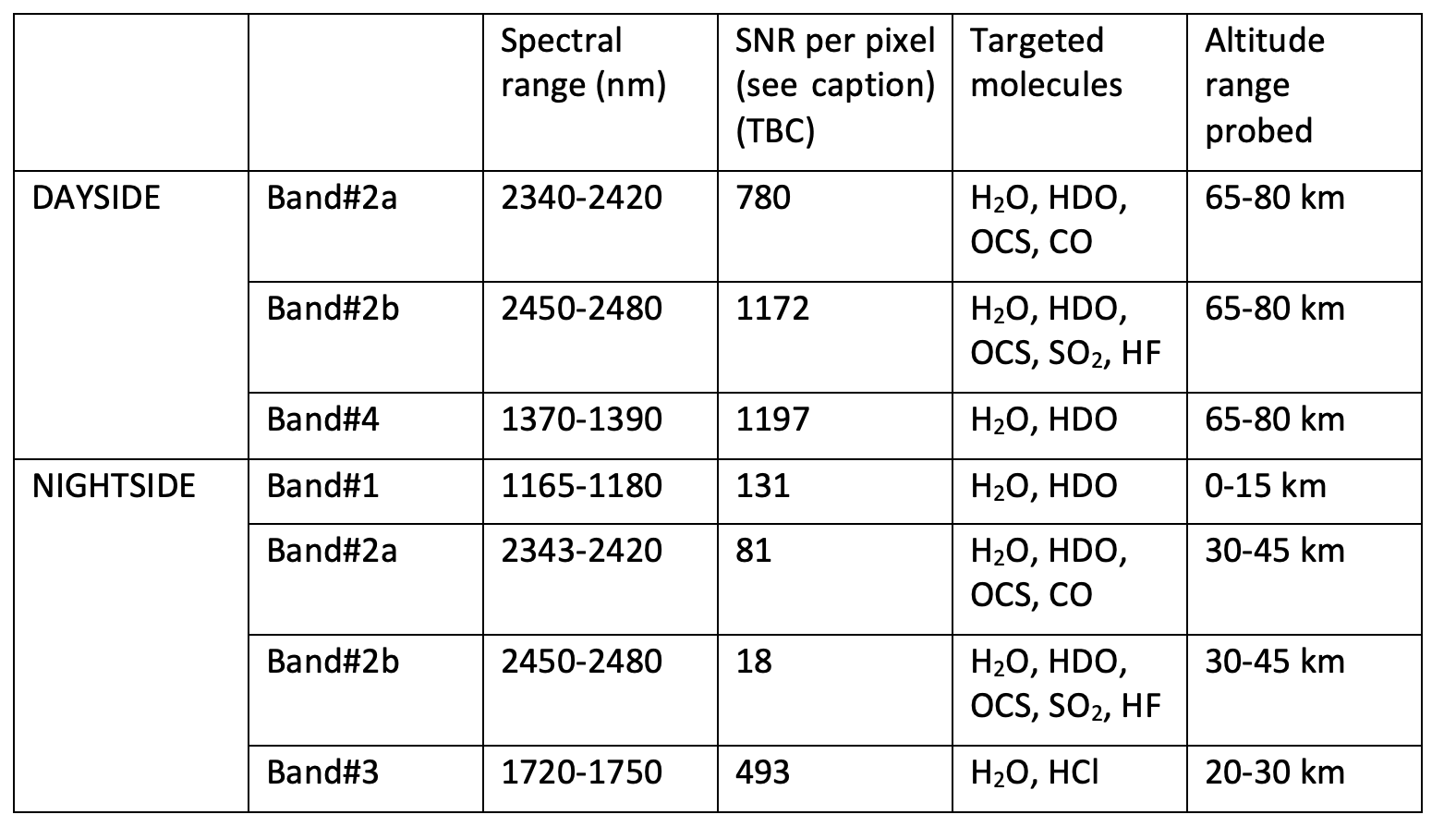
In VenSpec-H four spectral regions of interest are defined: band 1 (1.16 to 1.18 µm), band 2 (2.34 to 2.48 µm), band 3 (1.72 to 1.75 µm) and band 4 (1.37 to 1.39 µm). In order to reduce instrument complexity, band 2 will be further subdivided in band 2a (2.34 to 2.42 µm) and band 2b (2.45 to 2.48 µm). Bands 1, 2a, 2b and 3 will be observed on the night side, bands 2a, 2b and 4 on the dayside. Table 1 gives an overview of the species that can be measured in each band.
Functional description
Figure 1 gives the functional block diagram of the VenSpec-H instrument.
VenSpec-H is composed of:
- a warm section that contains the main base plate and the overall cover of the instrument;
- a cooled optical bench (also called “the cold section”) mounted inside the warm section (warm and cold section form together the main instrument);
- an electronic box (separated from the main instrument).
The warm base plate interfaces to the S/C deck by means of 3 kinematic mounts. It carries the cold section. The warm section contains the instrument entrance (nadir aperture). In front of the cold section a first part of the band selector is mounted, a filter wheel with 4 filters and associated optics. At the exit of the cold section a detector-cooler assembly is mounted with its proximity electronics.
A shutter mechanism is foreseen to close off the instrument aperture and to protect the instrument during aerobraking.
The optical bench (cold section) contains a cooled spectrometer. The entrance of the cold section is a rectangular slit that is part of a filter-slit-assembly. The image of the slit is projected on the spectrometer. The filter on the filter-slit-assembly consists of an upper and a lower zone that and is part of the band selection of the instrument, together with the filters in the filter wheel (hence, the band selector is partly in the warm, partly in the cold section). Filters and slit are deposited together on a carrier substrate. The spectrometer consists further of a parabolic mirror (rendering the incoming light parallel), a free form corrector plate (correcting the aberrations of the parabolic mirror), an echelle grating (spectral diffraction of the light), a detector optics unit (collimating the diffracted light on the detector). The optical path contains a number of folding mirrors to reduce the size of the spectrometer section.
The cold section is cooled down by means of a cold section radiator to -45 °C. The warm baseplate is kept at approximately 0 °C by means of a warm section radiator.
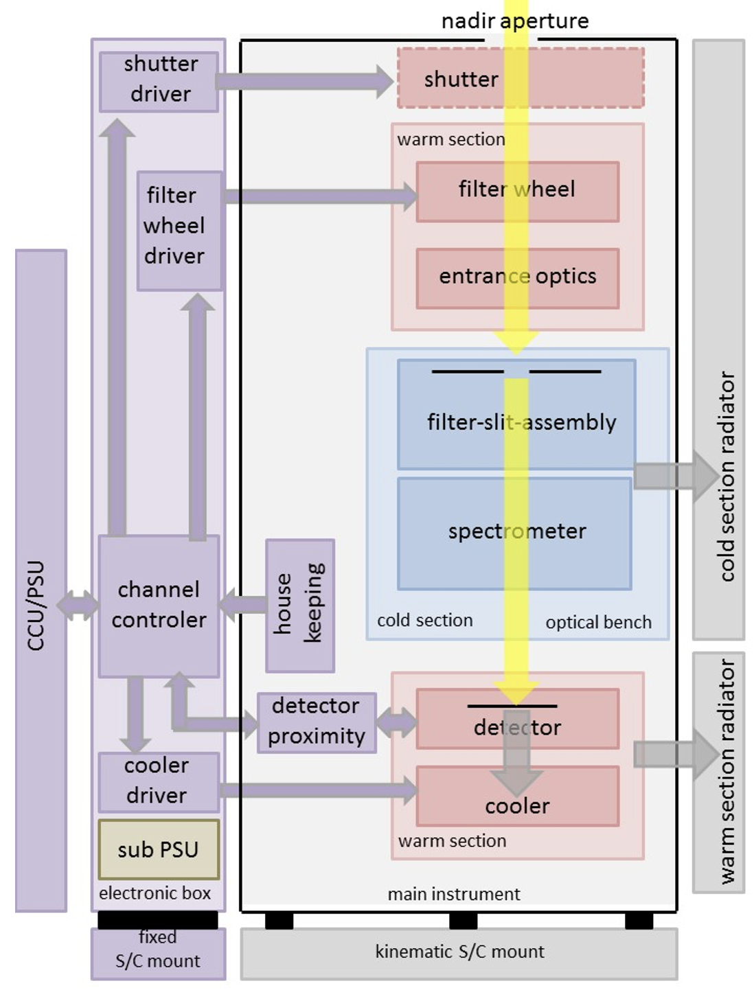
The detector is an Integrated Dewar Detector-Cooler Assembly (IDDCA). The dewar window sits in the exit aperture of the cold section. The Focal Plane Array (FPA) is located a bit further in the focal plane of the detector optics. The FPA is cooled by means of a cryocooler.
The VenSpec-H electronics (lodged in a dedicated unit and mounted separately to the S/C deck) consist of a channel control unit (CCC), a motor driver unit (MOD) that drives the filter wheel driver, the cryocooler and the shutter, and a Detector control unit (DEC) that interfaces with the detector and its proximity electronics (DEP). The VenSpec-H electronics interface with the Central Control Unit (CCU) and Power Supply Unit (PSU) of the VenSpec-suite. It contains a so called sub-PSU that receives primary power from the central VenSpec-PSU and provides secondary power to the VenSpec-H instrument.
Thermo-mechanical configuration
VenSpec-H consists of two units, the optical bench (also called “main instrument”) and a detached electronic box (further called E-Box). The reason for separating the electronics is to avoid the injection of heat dissipated by the electronic boards into the optical bench that needs to be cool and thermally stable.
The optical bench is composed of a cold section (the spectrometer part) and a warm section. The cold section is cooled down to -45 °C by means of passive cooling. A cold finger is attached to a thermal connector at the rear of the cold section and connected via a strap and a heat pipe to an external S/C radiator. Similarly, also the warm section is passively cooled down to a range between 0 and +10 °C. It has a thermal connector as well, where a strap is attached that is connected to a second S/C radiator. Cooling the instrument, and especially the spectrometer part, is crucial to avoid perturbation of the spectral measurements by the instrument’s proper infrared radiation.
VenSpec-H can be seen as a box-in-a-box construction, the inner box being the cold section and mounted inside the outer box, being the warm section (Figure 2). Both boxes are made from aluminum and are completely wrapped in MLI to limit as much as possible radiative heat exchange between cold section and warm section at one hand, and between warm section and S/C at the other hand.
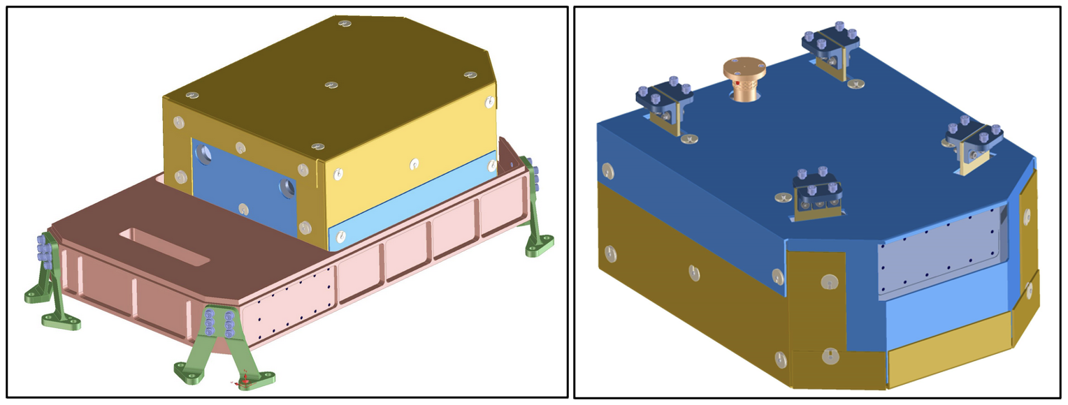
Figure 2. Left: top view showing cold section (wrapped in MLI (orange + blue) and mounted onto the warm baseplate (red)). The attachment zone for the thermal connector is visible at the long side of the warm base plate. Right: bottom view of cold section showing 4 flexures and fixed pin and rear attachment zone for thermal connector.
The two boxes are also conductively decoupled from each other and from the S/C. The cold base plate is mounted on the warm base plate by means of four flexures (Figure 3). These flexures consist of titanium end fittings at either side and a thermally isolating vetronite plate in between. The flexures guarantee not only a good thermal decoupling, they serve also at absorbing thermo-elastic deformations. This is needed to keep the cold base plate aligned with the warm base plate. Movements of the cold base plate are mechanically constraint by choosing an appropriate orientation of the flexures and with the help of a fixed pin. This pin materializes an invariant point where cold and warm base plates are kept together. The location of the fixed pin is chosen such that the complete optical bench becomes as insensitive as possible to different temperatures of the warm section. Like the flexures, also the pin is a good thermal insulator.
The warm section, or in other words, the complete VenSpec-H instrument, is thermally decoupled from the S/C by means of four titanium V-shaped bi-pods (Figure 3). While this is not a real kinematic mount (there are four feet instead of three), it still offers good mechanical decoupling from the S/C deck. Together with the flexures between cold and warm box, these S/C feet help to achieve the required flatness of the optical bench and sufficient stability over the duration of a measurement.
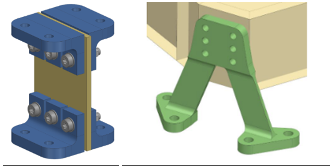
Figure 3. Left: one of four flexures between cold and warm section. Right: one of four V-shaped bi-pod interface feet to the S/C.
Shutter mechanism
During normal operation, i.e., from the start of the science phase onwards, light enters the instrument via a circular aperture in the front wall of the warm box. Before that, this aperture is closed off by a one-shot shutter mechanism, mounted right after the aperture (Figure 4). The shutter protects the optical elements in the interior of the instrument against contamination and atomic oxygen fluence during aerobraking.
The opening system of the shutter is based on the thermal knife principle. The shutter door is held by a polymer wire under spring tension. By applying electrical power to a resistor, the wire is melted, and the door turns to a position where it is no longer in the optical path. Two Hall-sensors detect the closed and open positions of the shutter. In the door an IR grade fused silica window is lodged. This is a fail-safe measure in case the shutter door would not open.
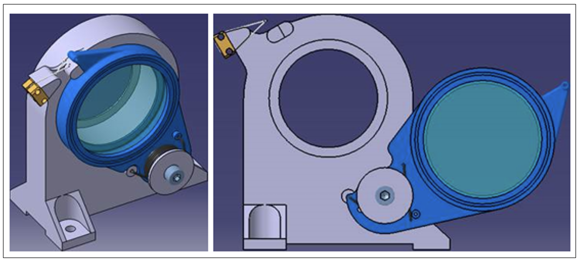
Figure 4. Shutter mechanism (left in closed position, right in open position)
Opto-mechanical configuration
The optical path of the VenSpec-H instrument is given in Figure 5.
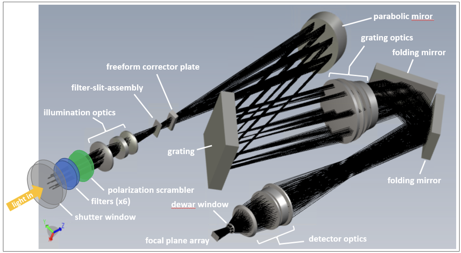
Figure 5. Optical path of the VenSpec-H instrument
The first optical element that is encountered is a filter wheel. It has eight positions, six of which carry filters. Besides the six filters there is also a closed and an open position foreseen in the wheel. The closed position will serve to perform dark measurements. Four of the six filters are so-called normal filters, each passing one of the four spectral bands of the instrument #1, #2, #3 and #4. The two other filters are polarizers, both vertically oriented and passing the two dayside spectral bands #2 and #4 (Figure 6). The wheel is capable to perform fast switching between filters, hence allowing quasi-simultaneous observations in the different spectral bands.
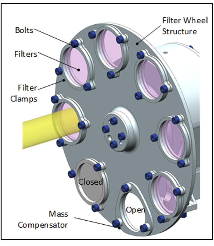
Figure 6. Filter wheel with eight positions
The filter wheel moves with respect to the fixed housing over a set of two ball bearings, each carrying 26 stainless steel balls with MoS2 coating. The wheel is driven by a stepper motor (gearless, 360 steps), commanded from the central channel controller in micro-stepping mode. Position referencing of the wheel is done by means of Hall-sensors.
Immediately after the filter wheel is located a polarization scrambler. This device desensitizes the instrument to polarization in the incoming light. The scrambler uses the babinet principle. Four fused silica wedges are stacked together in one opto-mechanical holder. The wedges are designed such that the inevitable altering of the line-of-sight of the instrument is kept within the overall pointing accuracy requirements of the instrument.
The illumination optics (Figure 7 left), situated just in front of the spectrometer, serves at focusing the incoming light beam onto the entrance of the spectrometer. This objective is composed of a triplet of all spherical lenses, made of multispectral ZnS, infrared grade fused silica and CaF2 respectively.
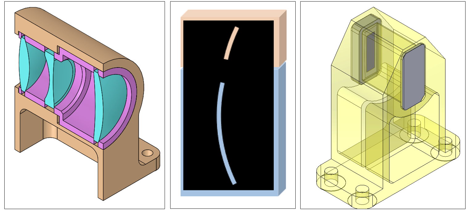
Figure 7. Left: cross-section of the illumination optics. Middle: filter-slit-assembly (exaggerated slit curvature). Right: holder with filter-slit-assembly (front) and freeform corrector plate (rear)
Filter wheel, polarization scrambler and illumination optics are all situated in the warm section of the instrument and together prepare the incoming light for further analysis in the cold spectrometer section.
The first element in the cold section of the instrument is the filter-slit-assembly (Figure 7 middle). The filter wheel carries a filter that passes the complete spectral band #2 to the spectrometer. However, band #2 is too large to fit in one grating order. Still, it is required to measure the complete band at the same time. Therefore, it is split in two horizontal strips #2a and #2b, one above the other, in the filter-slit-assembly. Between the strips is a transition zone that cannot be used. Band #2a travels through the top of the spectrometer, band #2b through the bottom, and both bands are simultaneously imaged in the top and bottom zone of the detector. This dual filter is placed at the position of the entrance slit of the spectrometer to have the boundary between the strips sharply imaged on the detector. The filter strips both have a good transmission for the wavelengths of bands #1, #3 and #4. They are both half passband with cut-off resp cut-on in the middle of band #2.
The filter-slit-assembly is an IR grade fused silica plate to which the horizontal filter strips are deposited. Since ideally the dual filter is located at the entrance slit position of the spectrometer, the titanium black slit is deposited on the same plate as the filters. The dimensions of the slit are chosen such that the detector image of the slit has the full detector height and is one pixel wide. To compensate for smile introduced by the grating, the slit is curved so that the image of the slit is straight within one pixel. The slit is closed in the region where crosstalk between the filters is anticipated.
The light that enters through the slit must be collimated again towards the grating. To that end, an off-axis parabolic mirror is used that reflects the light beam at an angle of sixteen degrees with the incident beam (Figure 8 left). The mirror is a monolithic aluminum part.
Since the spectrometer slit is quite long, a compensation is needed for the aberration introduced by the parabolic mirror for field points not in the center of the slit. This is done by means of an aspheric freeform corrector plate, made from IR grade fused silica, placed shortly after the slit. The freeform corrector plate is mounted together with the filter-slit-assembly in one opto-mechanical holder (Figure 7 right).
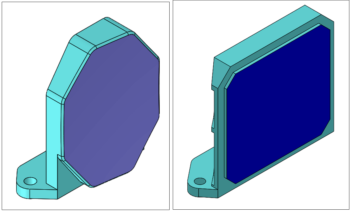
Figure 8. Left: parabolic mirror. Right: echelle grating.
As diffractive element a ruled echelle grating is used with periodic reflecting step (Figure 8 right). The grating is a monolithic element, built in the RSA 443 alloy. A layer of NiP-plating is applied on the optical surface before ruling, so that a better surface roughness and, hence, better straylight performance, is obtained.
The diffracted light from the grating must be focused onto the detector. To that purpose the optical path after the grating contains two sets of lenses, separated by two folding mirrors. The grating optics, closest to the grating (Figure 9 left), is a quadruplet of a Schott IRG 27, a multispectral zinc sulphide, a Schott IRG 22 and an infrared grade fused silica lens. The detector optics, closest to the detector (Figure 9 right), is a quadruplet of a multispectral zinc sulphide, a Schott IRG 24, and two Schott IRG 27 lenses. The two folding mirrors are monolithic aluminum parts (Figure 9 middle).
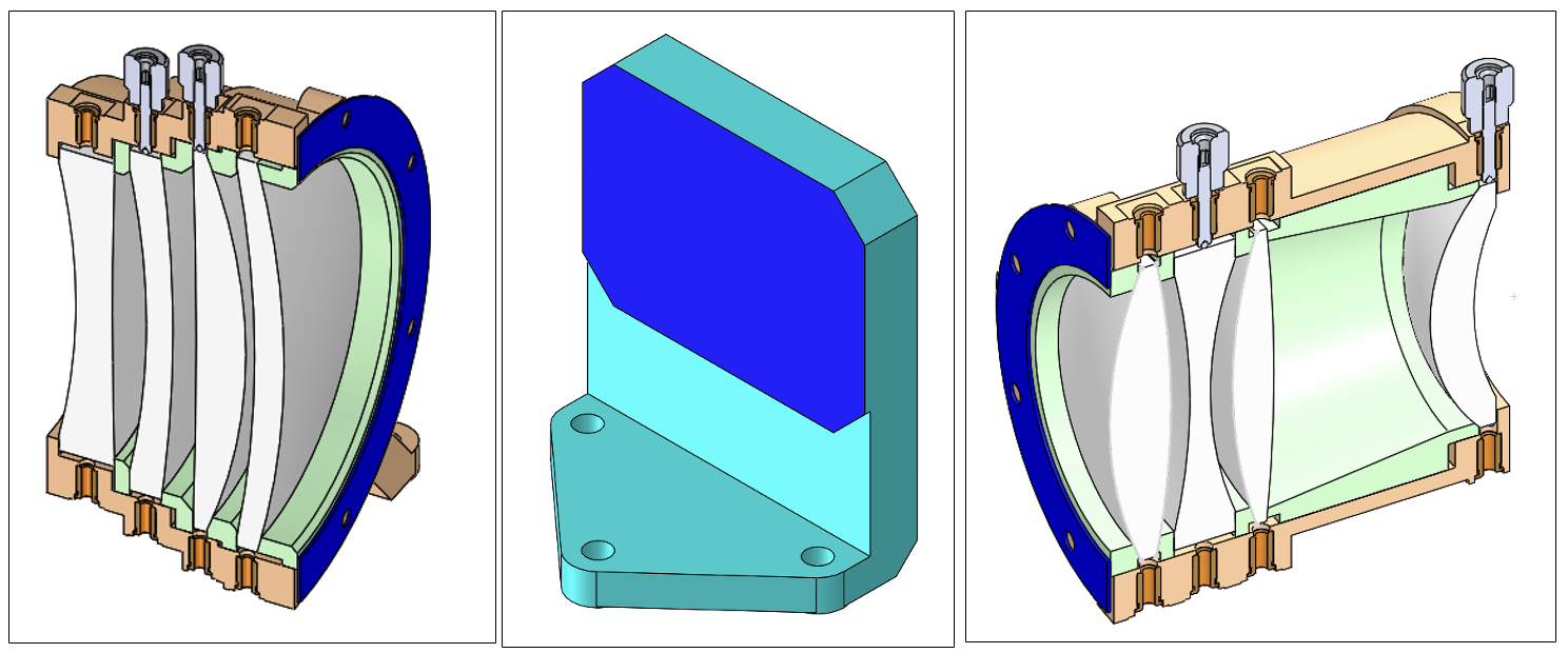
Figure 9. Left: grating optics. Middle: one of two folding mirrors. Right: detector optics.
Detector configuration
The diffracted light leaves the cold section and enters immediately in the detector assembly that sits right after the spectrometer exit in the warm section. The detector is a Mercury Cadmium Telluride 384×288 SWIR detector with a linear Stirling cryocooler, cooling down the detector to approximately 135 K. The focal plane array consists of an infrared matrix detector and a specific read-out multiplexer hybridized to the infrared detector. This hybrid assembly is mounted inside a hermetically sealed vacuum dewar. The dewar has an entrance window and houses a cold shield that reduces infrared background and stray light radiation.
The read-out integrated circuit that is connected to the focal plane array can read out the pixels at 10 MHz, corresponding to 450 full detector frames per second. The pixel data are converted into eight analog data streams presented at the electrical interface of the read-out integrated circuit. The parameters of the detector are programmable via a serial peripheral interface (SPI). Figure 10 shows the electrical block diagram of the focal plane array with its read-out integrated circuit.
Close to the read-out circuit, but just outside the dewar, is located the detector proximity electronics board. Here the eight single-ended analog output signals of the detector are transformed into differential signals and transmitted to the detached E-Box.
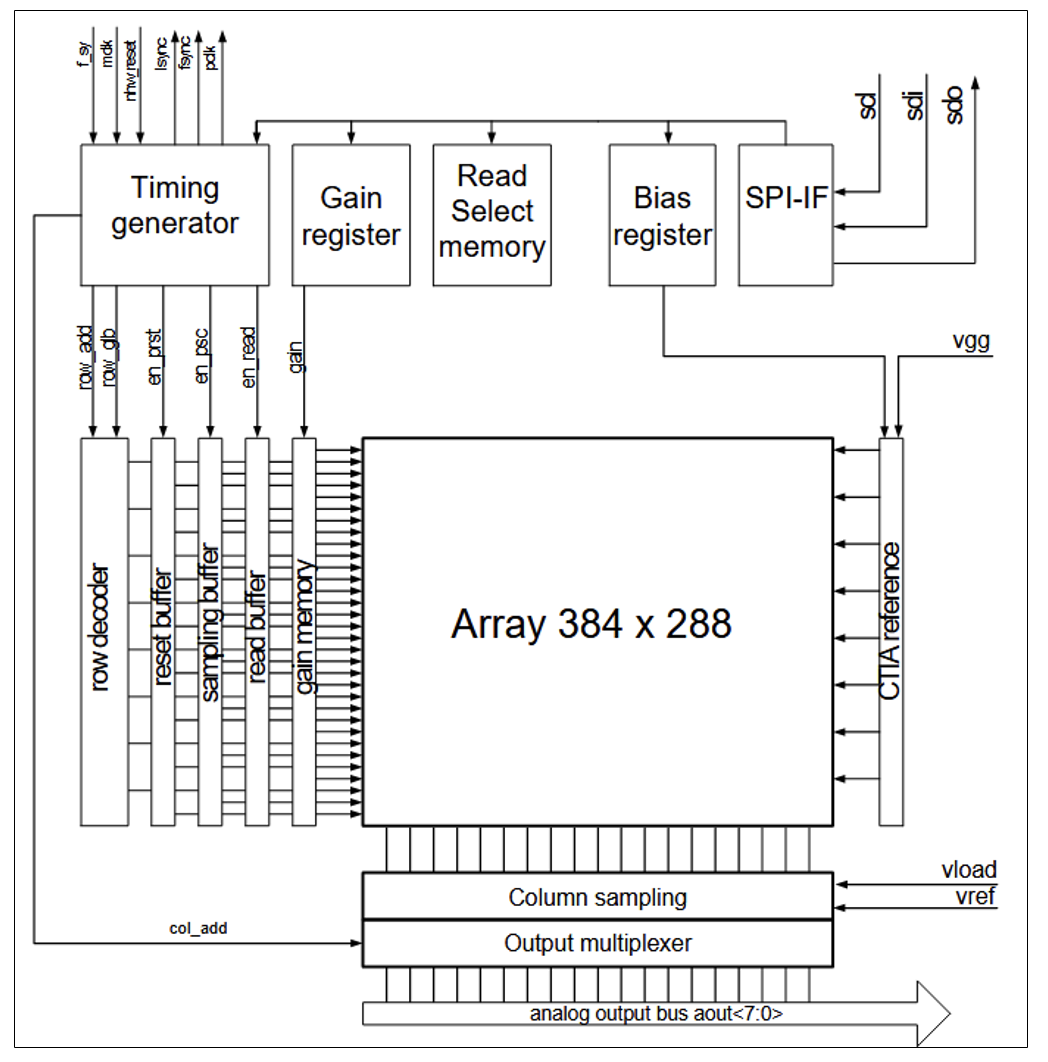
Figure 10. Focal plane array with read-out integrated circuit.
Electronics configuration
The electronic connection diagram is given in Figure 11.
Except the detector’s proximity electronics, all other electronic modules are detached from the optical bench and housed in a separate box. The E-Box is a stack of four aluminum frames, each carrying one board (Figure 12). From top to bottom, the boards in the electronic box are: the processor board, the FPGA board, the motor driver board, and the power supply unit.
The processor board is built around a Cortex-M7 microprocessor. The processor forms the central intelligence of the instrument. It realizes the interlink between the central VenSpec CCU at one end, and the subsystems of VenSpec-H at the other end. Its main tasks are: receiving of commands from the CCU, controlling the mechanisms and the detector, collecting the detector and the housekeeping data, and transmitting the data to the CCU. For external and internal communication bi-directional SpaceWire lines are used.
Several analog-to-digital convertors are foreseen to collect and convert the housekeeping signals via serial peripheral interface buses from everywhere in the instrument (temperatures, voltages, currents, and position sensors).
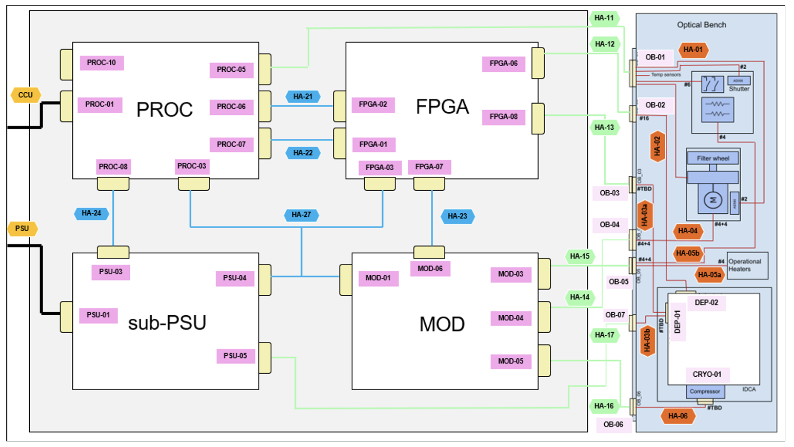
Figure 11. Electrical connection diagram.
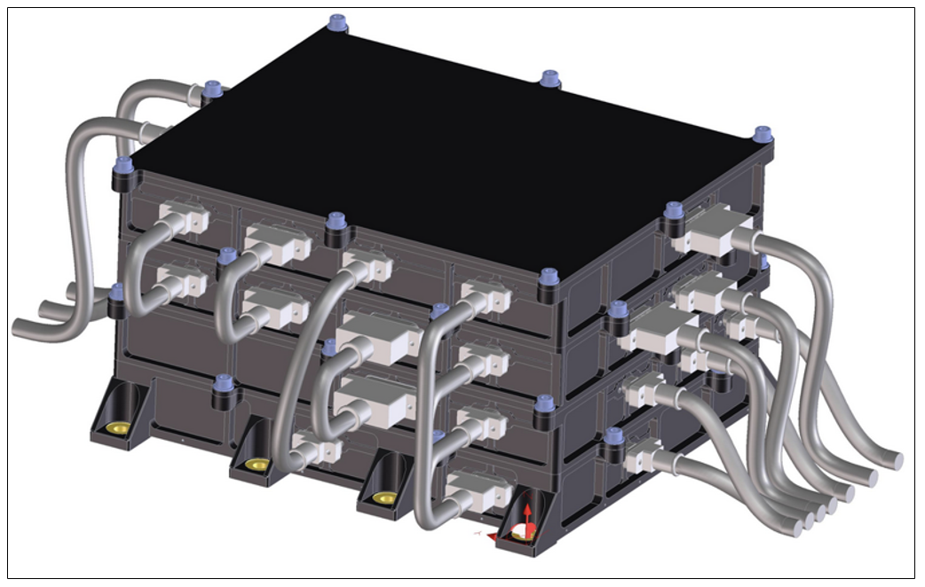
Figure 12. The E-Box.
The FPGA board is the electronic work zone of the instrument. The analog differential data signals from the detector arrive on this board over eight lines and are then converted at high speed into digital values. Single detector frames are temporarily stored in random-access memory inside the FPGA to allow for fast on-the-fly binning, accumulation, and background subtraction during the measurements.
As soon as a data frame has been finished, it is transferred to static imaging memory, external to the FPGA, or it is transmitted immediately over SpaceWire to the processor board. From the FPGA board also the pulse-width-modulated control signals for the cryocooler and filter wheel motors are produced.
The motor driver board contains the power drivers for the filter wheel motor and the cryocooler compressor, the power section of the operational heaters and the shutter activation electronics.
The nominal and redundant drivers of the filter wheel are based on a full bridge driver circuit in combination with four switching N-channel power MOSFETs. They are fed by the pulse-width-modulated signal generated in the FPGA. The same topology is used for the driver of the cryocooler.
For storing the on-board processor software and FPGA firmware, magneto-resistive memory devices are installed on the processor board. A first memory device is configured as (re)programmable memory and is used to boot in nominal situations. It contains a bootloader, the running version of the processor software and the FPGA bitstream. A second memory device is configured as a read-only non-volatile memory and is used to boot in contingency situations. It contains a redundant bootloader, the fail-safe version of the processor software and of the FPGA bitstream.
The bottom frame of the electronic box contains the power supply unit (sub-PSU board) of the VenSpec-H instrument. It receives the primary 28 V power line from the S/C and transforms it in secondary voltages (+3.3V, +/-12V, a regulated +28V and an isolated +8V) that are used throughout the instrument.
On-board software and firmware configuration
The on-board firmware block diagram is given in Figure 13.
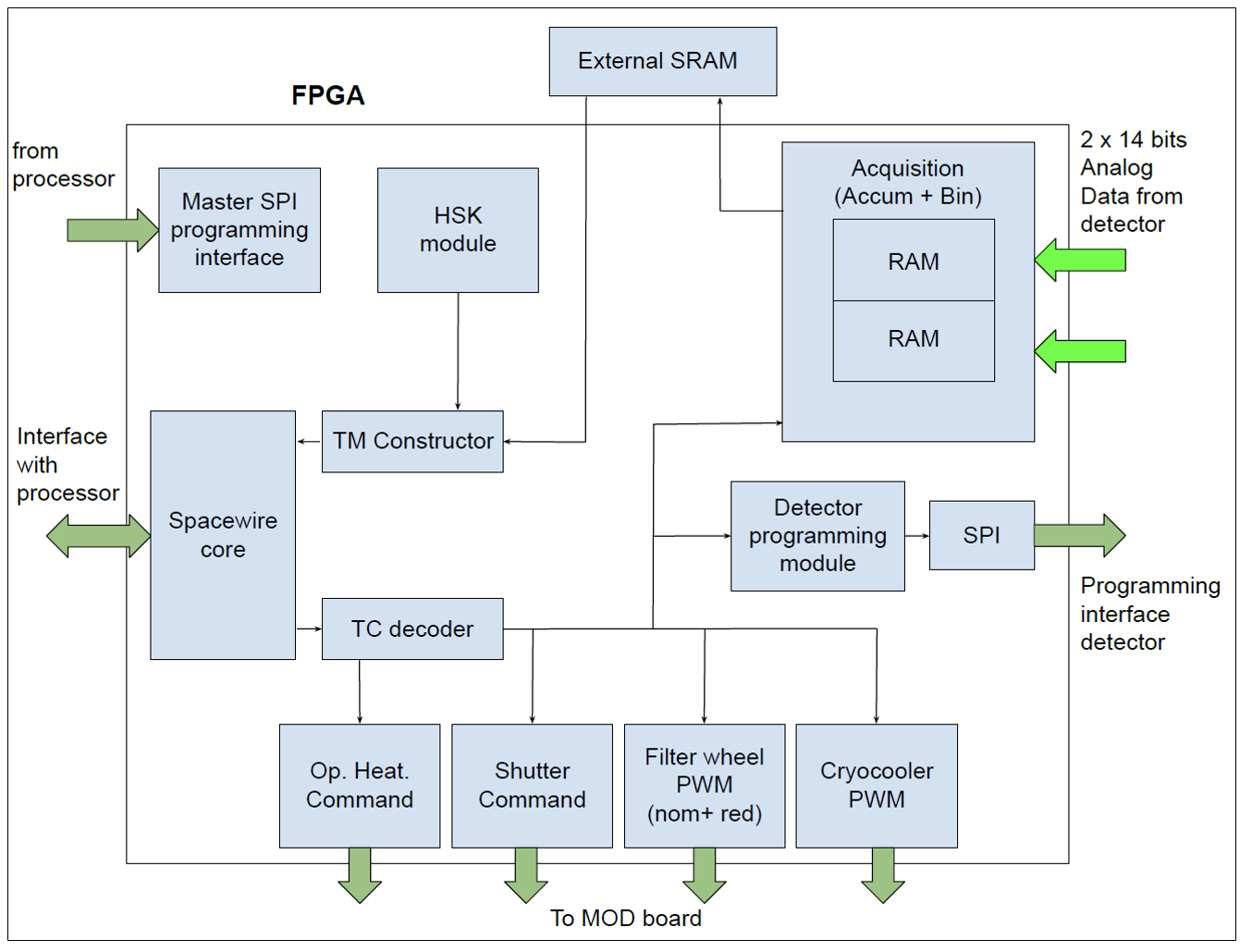
Figure 13. On-board firmware block diagram.
The processor on the processor board is the board computer of the instrument. The Python-written on-board software that runs in the processor coordinates and times all the tasks that need to be performed, and it manages the external communication (command receiving and data transmitting) with the CCU.
The on-board VHDL-written firmware in the FPGA on the FPGA board links the hardware subsystems to the processor. It translates the commands received from the processor into hardware actions and transmits the data resulting from these actions back to the processor. The on-board firmware (Figure 13) executes the following tasks: powering on/off the operational heaters, activating the shutter mechanism, generating the control signals for the cryocooler driver, placing the filter wheel in the requested position, programming the detector parameters, retrieving and handling the detector data, and measuring local housekeeping.